

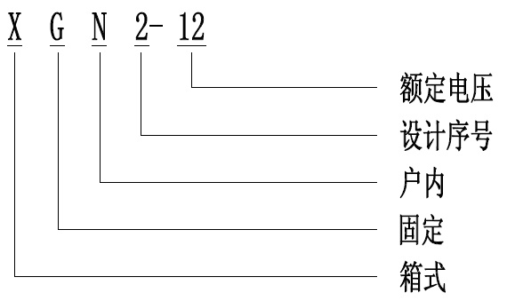
Xgn2-12 box type fixed indoor AC metal enclosed switchgear
Classification:
High voltage switch cabinet
Performance characteristics ● the switch cabinet is a metal enclosed box structure, and the cabinet frame is welded by angle steel. The cabinet is divided into circuit breaker room, bus room and relay room, which are separated by steel plate; ● the circuit breaker room is in the middle of the cabinet, the circuit breaker is integrated with the operating mechanism, the upper wiring terminal of the circuit breaker is connected with the lower wiring terminal of the disconnector, and the lower wiring terminal of the circuit breaker is connected with the current transformer. The circuit breaker room is equipped with a pressure release channel. If an internal arc occurs, the gas can release the pressure through the exhaust channel; ● the busbar room is at the rear upper part of the cabinet body. In order to reduce the height of the cabinet body, the busbar is arranged in shape and supported by insulators, and the busbar is connected with the wiring terminal on the disconnector; ● the cable room is behind the lower part of the cabinet. The cable room is equipped with a live sensor to detect the primary voltage, and the cable is fixed on the support. When the main wiring is the connection scheme, this room is the connection bus room; ● the operating mechanism of the circuit breaker is on the left side of the front, and above it is the operation and interlocking mechanism of the disconnector; ● the switch cabinet is double-sided maintenance. The front is used to repair the secondary components of the relay room, the maintenance operating mechanism, mechanical interlocking and transmission part, and the circuit breaker. The back is used to repair the main bus and cable terminals. The circuit breaker room is equipped with lights; ● a grounding bus parallel to the cabinet width direction is set under the front door; ● the switch cabinet adopts mechanical interlocking device, which simply and effectively meets the "five prevention requirements", that is, to prevent the live load from opening and closing the disconnector; Prevent false opening and closing of circuit breaker; Prevent from entering the charged Bay by mistake; Prevent the grounding switch from being closed with electricity; Prevent closing and energizing with grounding knife. The operating principles of mechanical interlocking are as follows: (1) Live operation (operation → maintenance) The switch cabinet is in the working position, that is, the disconnector and circuit breaker are in the closing state, the front and rear doors are closed, locked and in live operation, and the small handle is in the working position at this time. Live operation must be carried out in strict sequence: ① Circuit breaker breaking; ② Turn the small handle to the "opening and locking" position, and the circuit breaker cannot be closed at this time; ③ Insert the handle into the isolation operation hole and pull it from top to bottom to the isolation opening position; ④ Turn the small handle to the "maintenance" position, first open the front door, take out the rear door key, open the rear door, and the power failure operation is completed. The maintenance personnel can maintain and repair the circuit breaker and cable room. (2) Power transmission operation (maintenance → operation) If power transmission is required after maintenance, the operation procedures are as follows: ① Close and lock the rear door; ② Take out the key and close the front door; ③ Pull the small handle from the maintenance position to the opening and locking position, and then the front door is locked; ④ Insert the operating handle into the operating hole of the disconnector and push it from bottom to top to make the upper disconnector in the closing position; ⑤ Take out the operating handle and turn the small handle to the working position. At this time, the circuit breaker can be closed. Product model
ContactProduct details
Performance characteristics
● the switch cabinet is a metal enclosed box structure, and the cabinet frame is welded by angle steel. The cabinet is divided into circuit breaker room, bus room and relay room, which are separated by steel plate;
● the circuit breaker room is in the middle of the cabinet, the circuit breaker is integrated with the operating mechanism, the upper wiring terminal of the circuit breaker is connected with the lower wiring terminal of the disconnector, and the lower wiring terminal of the circuit breaker is connected with the current transformer. The circuit breaker room is equipped with a pressure release channel. If an internal arc occurs, the gas can release the pressure through the exhaust channel;
● the busbar room is at the rear upper part of the cabinet body. In order to reduce the height of the cabinet body, the busbar is arranged in shape and supported by insulators, and the busbar is connected with the wiring terminal on the disconnector;
● the cable room is behind the lower part of the cabinet. The cable room is equipped with a live sensor to detect the primary voltage, and the cable is fixed on the support. When the main wiring is the connection scheme, this room is the connection bus room;
● the operating mechanism of the circuit breaker is on the left side of the front, and above it is the operation and interlocking mechanism of the disconnector;
● the switch cabinet is double-sided maintenance. The front is used to repair the secondary components of the relay room, the maintenance operating mechanism, mechanical interlocking and transmission part, and the circuit breaker. The back is used to repair the main bus and cable terminals. The circuit breaker room is equipped with lights;
● a grounding bus parallel to the cabinet width direction is set under the front door;
● the switch cabinet adopts mechanical interlocking device, which simply and effectively meets the "five prevention requirements", that is, to prevent the live load from opening and closing the disconnector; Prevent false opening and closing of circuit breaker; Prevent from entering the charged Bay by mistake; Prevent the grounding switch from being closed with electricity; Prevent closing and energizing with grounding knife. The operating principles of mechanical interlocking are as follows:
(1) Live operation (operation → maintenance)
The switch cabinet is in the working position, that is, the disconnector and circuit breaker are in the closing state, the front and rear doors are closed, locked and in live operation, and the small handle is in the working position at this time. Live operation must be carried out in strict sequence:
① Circuit breaker breaking; ② Turn the small handle to the "opening and locking" position, and the circuit breaker cannot be closed at this time; ③ Insert the handle into the isolation operation hole and pull it from top to bottom to the isolation opening position; ④ Turn the small handle to the "maintenance" position, first open the front door, take out the rear door key, open the rear door, and the power failure operation is completed. The maintenance personnel can maintain and repair the circuit breaker and cable room.
(2) Power transmission operation (maintenance → operation)
If power transmission is required after maintenance, the operation procedures are as follows:
① Close and lock the rear door; ② Take out the key and close the front door; ③ Pull the small handle from the maintenance position to the opening and locking position, and then the front door is locked; ④ Insert the operating handle into the operating hole of the disconnector and push it from bottom to top to make the upper disconnector in the closing position; ⑤ Take out the operating handle and turn the small handle to the working position. At this time, the circuit breaker can be closed.
Product model
Related products


 ABOUT US
 PRODUCT
 CASE
CASE 联系我们
联系我们Add:No. 99, Guanyu Road, high tech Development Zone, Xiangyang City (in the Institute of Hubei tieneng Electric Group)


Focus on us
Mobile website